


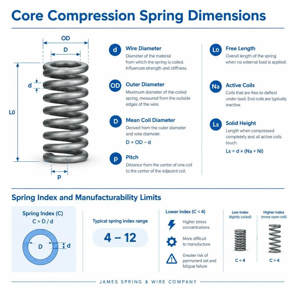
Fundamental Sizing and Dimensional Parameters
Understanding the fundamental dimensions of a compression spring is paramount for any engineering application. These parameters dictate not only the physical fit but also the spring’s performance characteristics, including its load capacity, deflection, and operational lifespan. The primary dimensions to consider are wire diameter, outer diameter, and free length.
Wire Diameter (d): This is the diameter of the material from which the spring is coiled. It is a critical factor influencing the spring’s strength and stiffness. A larger wire diameter generally results in a stiffer spring capable of handling heavier loads. Standard wire diameters are often specified in gauges (e.g., AWG, SWG) or in decimal inches/millimeters.
Outer Diameter (OD): This is the maximum diameter of the coiled spring, measured from the outside edges of the wire. The outer diameter is crucial for ensuring the spring fits within its designated housing or over a guide rod. The mean coil diameter (D) is often used in calculations and is derived by subtracting the wire diameter from the outer diameter (D = OD – d).
Free Length (L0): This refers to the overall length of the spring when no external load is applied. It is measured from end to end. The free length, in conjunction with the number of coils and wire diameter, determines the spring’s potential deflection and its solid height.
Pitch (p): The pitch is the distance from the center of one coil to the center of the adjacent coil. It is a key factor in determining the spring’s stiffness and the amount of space available for deflection between coils. For springs with closed and ground ends, the pitch is typically calculated by dividing the effective coil length by the number of active coils.
Active Coils (Na): Not all coils in a spring contribute to its deflection. Active coils are those that are free to deflect under load. End coils, especially those that are closed and ground, are generally considered inactive as they primarily serve to provide stable bearing surfaces. The number of active coils significantly impacts the spring rate.
Solid Height (Ls): This is the length of the spring when it is compressed completely, so that all active coils are touching. It is calculated by multiplying the wire diameter by the total number of coils (active plus inactive). Designing a spring that never reaches its solid height under normal operating conditions is crucial to prevent premature failure due to overstressing.
The interplay of these dimensions is complex, and even slight variations can significantly alter a spring’s behavior. For instance, increasing the wire diameter or decreasing the outer diameter (while keeping wire diameter constant) will generally increase the spring’s stiffness. Conversely, increasing the number of active coils or the free length will typically make the spring softer.
Spring Index and Manufacturability Limits
The spring index (C) is a dimensionless ratio calculated by dividing the mean coil diameter (D) by the wire diameter (d) (C = D/d). This ratio is a fundamental indicator of a spring’s geometry and has profound implications for its performance, stress distribution, and, critically, its manufacturability.
A spring index typically ranges from 4 to 12. Springs with a low index (e.g., C < 4) are considered “tightly coiled.” They often experience high stress concentrations on the inside diameter of the coil, making them difficult to manufacture without cracking or deforming the wire. This increased stress is accounted for by factors like the Wahl factor or Bergsträsser factor, which are multipliers applied to the basic stress equations to provide a more accurate stress calculation. Low index springs are also prone to permanent set and fatigue failure due to these localized high stresses.
Conversely, springs with a high index (e.g., C > 12-15) are “loosely coiled.” While they generally have lower stress concentrations and are easier to manufacture from a wire-forming perspective, they can be unstable. High index springs are more susceptible to buckling, especially if their free length is significantly greater than their mean coil diameter. They may also be more challenging to handle and can tangle easily.
From a manufacturing standpoint, tooling limits play a significant role. Spring coiling machines are designed to work optimally within certain spring index ranges. Extremely low or high index values may require specialized tooling, slower production speeds, or even make the spring impossible to produce with standard methods. Therefore, designing within a reasonable spring index range (typically 6 to 10) often leads to more cost-effective and reliable springs. Understanding the spring index is vital not just for performance prediction but also for ensuring the spring can be produced efficiently and consistently.
End Configurations and Geometric Tolerancing
The ends of a compression spring are critical for its stability, load application, and overall performance. The most common end configurations are:
- Open Ends (Untouched): The wire is simply cut, leaving the end coil open. These are the least expensive but offer the least stable seating surface, often causing the spring to tilt.
- Closed Ends (Untouched): The pitch of the end coils is reduced so that they touch the adjacent coil. This provides a flatter, more stable bearing surface than open ends but is not perfectly square.
- Closed and Ground Ends: The end coils are closed, and then the ends are ground flat and square to the spring’s axis. This is the most common and preferred configuration for critical applications as it provides maximum stability, reduces buckling tendencies, and ensures a more uniform load distribution.
- Open and Ground Ends: Less common, the end coils are open but ground flat. This might be used in specific applications where the spring needs to hook onto something but also requires a flat seating.
The choice of end configuration directly influences the number of active coils and the spring’s free length. Closed and ground ends typically add two inactive coils to the total coil count.
Geometric tolerancing for compression springs ensures that the manufactured spring meets specific dimensional and functional requirements. Key tolerances include:
- Free Length Tolerance: Specifies the permissible variation in the spring’s free length.
- Outer Diameter Tolerance: Defines the acceptable range for the spring’s OD.
- Squareness of Ends: Crucial for stability, this tolerance dictates how perpendicular the end-bearing surfaces are to the spring’s axis. Poor squareness can lead to eccentric loading and buckling.
- Pitch Variation: While not always explicitly toleranced for every coil, consistent pitch is essential for uniform stress distribution and predictable spring rate. Significant pitch variation can lead to localized stress concentrations.
- Axial Alignment: Related to squareness, this ensures the spring remains centered and does not lean within its assembly.
Industry standards, such as those from ASTM (e.g., ASTM A228 for hard-drawn spring wire) and ISO (e.g., ISO 10243 for compression springs for tool and die applications), provide guidelines for these dimensions and tolerances. Adhering to these standards helps ensure interchangeability, reliability, and consistent performance across different manufacturers and applications. Specifying appropriate tolerances is a balance between functional necessity and manufacturing cost, as tighter tolerances generally increase production complexity and expense.
Advanced Processes in Custom Spring Manufacturing
While standard spring manufacturing relies on established coiling techniques, custom spring production often incorporates advanced processes to meet stringent performance requirements. These processes are crucial for achieving specific material properties, enhancing durability, and ensuring the spring performs reliably under demanding conditions.

CNC Coiling: Modern custom spring manufacturing heavily relies on Computer Numerical Control (CNC) coiling machines. These sophisticated machines offer unparalleled precision and repeatability. Unlike older mechanical coilers, CNC machines can control multiple axes simultaneously, allowing for the creation of complex spring geometries, variable pitch, and intricate end forms with extreme accuracy. This digital control minimizes human error, reduces setup times, and ensures consistent quality across production batches, which is vital for high-performance applications.
Stress Relief: After coiling, springs inherently contain residual stresses induced by the cold-forming process. These stresses, if not relieved, can lead to premature fatigue failure, dimensional instability, and a phenomenon known as “set” (permanent deformation under initial load). Stress relief is a low-temperature heat treatment process (below the material’s critical temperature) that reduces these internal stresses without significantly altering the material’s hardness or microstructure. This process improves the spring’s elastic properties, dimensional stability, and fatigue life.
Heat Treatment: For certain materials, particularly those that are hardened and tempered, a full heat treatment process might be applied after coiling. This involves heating the spring to an elevated temperature (above the critical temperature), holding it, and then quenching it, followed by tempering. This process modifies the material’s microstructure to achieve desired hardness, strength, and toughness, which are critical for springs operating under high loads or in harsh environments.
Shot Peening: This is a cold working process used to improve the fatigue strength of springs. It involves bombarding the spring’s surface with small, spherical media (shot) at high velocity. The impact of the shot creates small indentations, which introduce compressive residual stresses on the surface of the spring. Since fatigue cracks typically initiate at the surface under tensile stress, these induced compressive stresses counteract the tensile stresses during operation, significantly increasing the spring’s resistance to fatigue failure and extending its lifespan.
Preset Removal (Scragging): Also known as presetting or scragging, this process involves compressing the spring to its solid height (or beyond, to a controlled extent) one or more times. The purpose of presetting is to induce controlled plastic deformation, which eliminates the tendency for the spring to “set” or lose free length during its initial operational cycles. By doing this in a controlled manufacturing environment, the spring’s final free length and load characteristics become more stable and predictable throughout its service life. This is particularly important for applications where precise load and deflection characteristics are critical over time.
Prototyping Stages in Custom Spring Manufacturing
The development of custom springs often involves a rigorous prototyping phase to validate design concepts and ensure optimal performance before full-scale production. This iterative process is crucial for mitigating risks and achieving precise specifications.
Rapid Prototyping: In the initial stages, rapid prototyping techniques allow engineers to quickly produce physical samples of a spring design. This might involve using advanced coiling machines for small batches or even additive manufacturing (3D printing) for complex wire forms, although the latter is less common for functional metal springs due to material properties. The goal is to obtain tangible parts for preliminary fit checks and basic functional assessments.
Design Iteration: Based on the initial prototypes, engineers conduct thorough evaluations. This often leads to design iterations, where parameters such as wire diameter, coil count, pitch, or material are adjusted to refine the spring’s characteristics. This iterative feedback loop between design and physical prototype is essential for optimizing performance, manufacturability, and cost-effectiveness.
Load Testing: One of the most critical aspects of prototyping is comprehensive load testing. Prototypes are subjected to various loads to measure their actual deflection, spring rate, and solid height. These empirical results are then compared against theoretical calculations and design specifications. Any discrepancies necessitate further design adjustments.
Prototype Verification: Beyond basic load testing, prototypes undergo rigorous verification processes. This includes dimensional inspection using precision tools, material analysis to confirm alloy composition and heat treatment effectiveness, and visual inspection for defects. The aim is to ensure that the prototype fully conforms to all specified engineering drawings and material requirements.
Cycle Testing: For applications requiring high durability and extended operational life, prototypes are subjected to extensive cycle testing. This involves repeatedly compressing and releasing the spring under simulated operating conditions for thousands or even millions of cycles. Cycle testing helps to identify potential fatigue failures, assess the spring’s long-term stability, and validate its expected lifespan. Data gathered from cycle testing is invaluable for predicting real-world performance and making final design refinements.
Quality Control Standards in Custom Spring Manufacturing
Maintaining high quality in custom spring manufacturing is paramount, especially given the critical nature of many spring applications. Adherence to established industry standards and rigorous quality control processes ensures that springs meet precise specifications and perform reliably.
Industry Standards: Several key industry standards govern the materials, manufacturing processes, and testing of compression springs. For instance, ASTM A228 specifies the requirements for hard-drawn carbon steel spring wire, a common material for compression springs. Other ASTM standards cover different spring materials and testing methods. ISO 10243 specifically addresses compression springs for tool and die applications, outlining dimensions, load ratings, and performance requirements. These standards provide a common language and set of benchmarks for manufacturers and users, ensuring consistency and reliability across the industry.
Load-Deflection Rate Verification: A fundamental quality check involves verifying the spring’s load-deflection rate (spring rate). This is typically performed using specialized spring testers that apply a known load and measure the resulting deflection, or vice-versa. The measured spring rate is then compared against the design specification. Deviations indicate issues with material properties, wire diameter, or coil geometry.
Dimension Verification: Precision measurement is crucial. Quality control technicians use a range of tools, including calipers, micrometers, optical comparators, and even coordinate measuring machines (CMMs), to verify critical dimensions such as wire diameter, outer diameter, free length, solid height, and squareness of ends. These measurements ensure the spring will fit correctly within its assembly and function as intended.
Non-Destructive Testing (NDT): For high-stress or critical applications, non-destructive testing methods may be employed to detect internal flaws or surface imperfections without damaging the spring. Techniques such as magnetic particle inspection (for ferromagnetic materials) or dye penetrant inspection (for surface cracks) can reveal defects that might lead to premature failure. Eddy current testing can also be used to detect surface cracks and material variations. These advanced checks ensure the structural integrity of the spring, especially when safety or performance under extreme conditions is a concern.
Stock vs. Custom Springs: Engineering Selection Criteria
The decision between using a stock compression spring or commissioning a custom-engineered solution is a critical one in mechanical design. It hinges on a balance of performance requirements, cost, lead time, and application specifics.
Stock Springs: These are pre-manufactured springs available off-the-shelf from catalogs or distributors. They come in a wide range of standard sizes, materials, and load ratings.
- Advantages:Cost-Effective: Generally much cheaper due to mass production.
- Availability: Readily available, offering short lead times.
- Simplicity: Easy to select from catalogs with published specifications.
- Disadvantages:Limited Options: May not perfectly match specific load, deflection, or space requirements.
- Compromises: Designers might need to compromise on performance or design to fit a stock spring.
- Suboptimal Performance: A “close enough” stock spring might lead to reduced efficiency, shorter lifespan, or unexpected failures in demanding applications.
Custom Springs: These are springs designed and manufactured to precise specifications for a particular application.
- Advantages:Optimized Performance: Tailored to exact load requirements, deflection, and operational environment, ensuring peak performance.
- Space Constraints: Can be designed to fit within tight or unusual spatial envelopes.
- Specialized Materials: Allows for the use of exotic alloys (e.g., Inconel, Titanium) for extreme temperatures, corrosive environments, or non-magnetic properties.
- Extended Fatigue Life: Advanced manufacturing processes and material selection can be optimized for maximum durability and cycle life.
- Unique Geometries: Can incorporate variable pitch, conical shapes, or other complex forms.
- Disadvantages:Higher Cost: More expensive due to design, tooling, and specialized manufacturing.
- Longer Lead Times: Requires design, prototyping, and production phases.
- Complexity: Requires engineering expertise for design and specification.
When to Choose Which:
- Stock Springs are ideal when:The application has flexible design parameters.
- Cost and lead time are primary concerns.
- Standard performance is sufficient.
- The operating environment is not extreme.
- Custom Springs are necessary when:Space constraints are tight, requiring a specific OD, ID, or free length.
- The spring must withstand dynamic fatigue over millions of cycles without failure.
- The application demands specialized alloys for corrosion resistance, high temperatures, or specific electrical/magnetic properties.
- The operating environment is extreme (e.g., cryogenics, vacuum, radiation, high vibration).
- Precise load-deflection characteristics are critical for system performance.
- A unique spring geometry is required.
Many engineering firms partner with a partner that manufactures standard and custom springs to meet diverse project needs. A company that provides a comprehensive guide to compression springs by size, covering both standard and bespoke options, can be an invaluable resource for designers.
Feature Stock Compression Springs Custom-Engineered Compression Springs Availability Off-the-shelf, immediate Made-to-order, requires lead time Cost Lower, economies of scale Higher, includes design, tooling, and specialized processes Lead Time Shortest Longer, due to design, prototyping, and production Design Flexibility Limited to catalog dimensions and specifications Unlimited, tailored to exact application requirements Performance Standard, may require design compromises Optimized for specific load, deflection, and environmental conditions Materials Common spring steels (e.g., music wire, stainless steel) Wide range, including exotic alloys for specific needs Tolerances Standard industry tolerances Tighter, application-specific tolerances possible Ideal Use Case General applications, prototyping, cost-sensitive projects Critical applications, unique space, extreme environments, high-cycle life Analyzing Load-Deflection Profiles
The load-deflection profile, or characteristic curve, of a compression spring is a graphical representation of how much force (load) is required to compress the spring by a certain distance (deflection). This relationship is fundamental to spring design and performance prediction.

At its core, the load-deflection behavior of a compression spring is governed by Hooke’s Law, which states that the force (F) required to extend or compress a spring by some distance (x) is proportional to that distance. Mathematically, F = kx, where ‘k’ is the spring rate or spring constant.
Spring Rate (k): This is a measure of the spring’s stiffness, expressed in units of force per unit length (e.g., lbs/in or N/mm). A higher spring rate indicates a stiffer spring, requiring more force to achieve a given deflection. The spring rate is primarily determined by the wire diameter, mean coil diameter, and the number of active coils. It can be calculated using the formula:
k = (G * d^4) / (8 * D^3 * Na)
Where:
G= Modulus of rigidity (material property)d= Wire diameterD= Mean coil diameterNa= Number of active coils
Initial Tension: While primarily associated with extension springs, compression springs can also exhibit a small amount of initial tension, especially if they are very tightly coiled. However, for most compression springs, the relationship between load and deflection is linear from the onset of compression, assuming no buckling occurs.
Linear Range: For a well-designed compression spring, the load-deflection curve is largely linear within its operational range. This means that for every unit of deflection, a consistent amount of additional load is required. This linear behavior simplifies design calculations and ensures predictable performance.
Deflection Limit: Every spring has a maximum safe deflection limit. Beyond this point, the material may yield, leading to permanent deformation (set), or the spring may reach its solid height. Operating a spring consistently near or at its solid height can lead to premature fatigue failure. The maximum allowable deflection is often specified as a percentage of the free length or as the distance to solid height minus a safety margin.
Understanding and accurately calculating the load-deflection characteristics for springs of different sizes is critical for ensuring that a spring will meet the force requirements of an application throughout its intended stroke, without overstressing the material or causing permanent damage. This analysis is a cornerstone of reliable mechanical design.
Critical Design Pitfalls and Sizing Verification
Even with careful planning, several common mistakes can undermine the performance and lifespan of compression springs. Recognizing these pitfalls and implementing robust verification methods are crucial for successful mechanical designs.
Buckling Risks: One of the most common failure modes for compression springs is buckling. This occurs when a spring, under axial compression, bows outwards like a column, losing its ability to apply force along its central axis. Factors contributing to buckling include a high slenderness ratio (free length to mean coil diameter), insufficient guidance, and excessive deflection.
- Prevention:Guide Rods/Pins: Using a rod through the inside diameter of the spring.
- Guide Tubes/Holes: Placing the spring inside a bore or tube.
- Reducing Slenderness Ratio: Designing springs with a shorter free length relative to their diameter.
- Proper End Conditions: Closed and ground ends provide better support and reduce buckling tendencies.
Resonance Vibration: If a spring’s natural frequency of vibration matches the frequency of an external force applied to it, resonance can occur. This leads to greatly amplified vibrations, high stresses, and rapid fatigue failure.
- Prevention:Frequency Analysis: Calculating the spring’s natural frequency and ensuring it is sufficiently far from operating frequencies.
- Damping: Introducing damping elements into the system.
- Variable Pitch: Designing springs with variable pitch can help broaden the frequency response and reduce the risk of resonance.
Solid Height Binding: Compressing a spring to its solid height, or even slightly beyond, can overstress the wire material, leading to permanent set or immediate failure. This often happens if the design does not account for manufacturing tolerances or unexpected overloads.
- Prevention:Adequate Clearance: Ensuring that the maximum required deflection leaves a sufficient gap before reaching solid height.
- Safety Factor: Applying a safety factor to the calculated solid height.
- Presetting: As discussed earlier, presetting during manufacturing can help stabilize the spring’s free length and resistance to set.
Measurement Verification: After manufacturing, verifying the spring’s dimensions and characteristics is essential to ensure it meets specifications.

- Free Length: Measured with a ruler or digital caliper.
- Outer Diameter/Inner Diameter: Measured with calipers or micrometers.
- Wire Diameter: Measured with a micrometer.
- Number of Coils: Counted visually.
- Squareness: Checked with a squareness gauge or by placing the spring on a flat surface and measuring any lean.
- Load Testing: Using a spring tester to verify the spring rate and load at specific deflections.
Common Spring Failure Modes:
- Fatigue Failure: Cracks initiating and propagating due to repeated stress cycles, often at stress concentrations or surface imperfections.
- Permanent Set: The spring does not return to its original free length after being compressed, indicating the material has yielded.
- Buckling: Axial instability causing the spring to bow.
- Corrosion: Degradation of material due to chemical reactions with the environment.
- Wear/Abrasion: Material loss due to friction with guide rods or housing.
- Fracture: Sudden breakage due to excessive stress, impact, or material flaws.
Frequently Asked Questions About Compression Spring Sizing
How is the spring index calculated and why is it important?
The spring index (C) is calculated by dividing the mean coil diameter (D) by the wire diameter (d): C = D / d. It is a crucial parameter because it directly influences the spring’s stress distribution, manufacturability, and susceptibility to buckling. A low spring index (typically below 4) indicates a tightly coiled spring, which can experience high stress concentrations on the inside of the coil, making it prone to cracking during manufacturing and reducing its fatigue life. Conversely, a high spring index (typically above 12-15) signifies a loosely coiled spring, which can be unstable and prone to buckling. The spring index helps engineers design springs that are both functional and feasible to produce, balancing performance requirements with manufacturing limits and stress concentration factors.
What causes spring buckling and how can it be prevented?
Spring buckling is a phenomenon where a compression spring, under axial load, bows or bends sideways rather than compressing linearly. It is primarily caused by a high slenderness ratio, which is the ratio of the spring’s free length to its mean coil diameter. If this ratio is too high, the spring acts more like a slender column and becomes unstable. Other contributing factors include inadequate guidance (lack of a guide pin or guide tube), uneven end conditions (poor squareness), and excessive deflection.
To prevent buckling:
- Use Guide Pins or Guide Tubes: These mechanical guides keep the spring aligned and prevent lateral movement.
- Optimize Slenderness Ratio: Design the spring with a lower free length-to-diameter ratio if space permits.
- Ensure Square Ends: Closed and ground ends provide a stable, perpendicular bearing surface, which helps maintain axial alignment.
- Limit Deflection: Do not compress the spring beyond its recommended operational deflection.
When should custom springs be chosen over standard catalog parts?
Custom springs should be chosen when standard catalog parts cannot meet the specific requirements of an application without compromise. This is typically necessary in situations where:
- Custom Envelope: The spring must fit within very tight or unusually shaped space constraints (e.g., specific outer diameter, inner diameter, or free length).
- Non-Standard Loads: The application requires precise load-deflection characteristics that are not available in stock springs, or demands very high/low loads for its size.
- Extreme Environments: The spring needs to operate reliably in harsh conditions such as very high or low temperatures, corrosive chemical environments, vacuum, or under specific electrical or magnetic requirements. This often necessitates specialized alloys (e.g., Inconel, Titanium, Beryllium Copper).
- Extended Fatigue Life: The application demands an exceptionally long operational life with millions of cycles, requiring optimized material, design, and manufacturing processes like shot peening or presetting.
- Unique Functionality: The spring requires complex geometry, variable pitch, or other features not found in standard offerings. While custom springs involve higher costs and longer lead times, they ensure optimal performance, reliability, and longevity for critical applications, preventing potential failures and costly redesigns down the line.
Conclusion
The meticulous sizing of compression springs is far more than a simple selection process; it is a critical aspect of precision engineering that underpins the reliability and performance of countless mechanical systems. From understanding the fundamental dimensional parameters like wire diameter, outer diameter, and free length, to appreciating the nuanced impact of the spring index on manufacturability and stress, every detail contributes to the spring’s ultimate success.
The decision to opt for stock springs versus custom-engineered solutions is dictated by a careful evaluation of application-specific needs, space constraints, and performance demands. When standard options fall short, custom manufacturing, with its advanced processes and rigorous quality control, offers the precision required for optimal functionality. By adhering to industry standards, verifying dimensions and load-deflection profiles, and proactively addressing potential design pitfalls like buckling or solid height binding, engineers can ensure dimensional accuracy and performance reliability. A thorough understanding of compression spring sizing and its associated engineering specifications is indispensable for achieving application success and ensuring the longevity of mechanical designs.
