


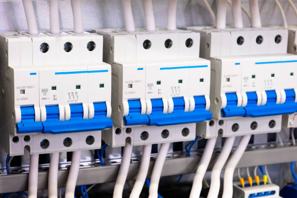
Commercial photovoltaic (PV) systems represent massive capital investments, engineered to generate sustainable yields over a 25-year lifespan. However, their vast physical footprint and exposed rooftop or ground-mount configurations make them highly vulnerable to atmospheric anomalies. Specifically, direct lightning strikes and induced transient overvoltages pose a constant, severe threat to operational continuity.
The heart of these installations relies on sophisticated inverters and Maximum Power Point Trackers (MPPT) to maximize power yield. These critical conversion nodes are built around highly sensitive power semiconductor elements, such as IGBTs and MOSFETs, which inherently possess exceptionally low dielectric breakdown thresholds.
When an unmitigated high-energy surge breaches these internal defenses, the microscopic semiconductor junctions are instantly punctured or cumulatively degraded. This electrical stress not only guarantees immediate hardware destruction but also leads to catastrophic operational downtime and immense replacement expenditures.
The Financial & Operational Impact of Transient Overvoltages
Direct Strikes vs. Induced Surges
A solar facility’s true risk profile depends entirely on the physics of the specific transient event. A direct lightning strike delivers massive, raw atmospheric energy, characterized mathematically by the 10/350 μs current waveform. This long-tail waveform represents a devastating, prolonged energy transfer capable of instantly vaporizing unprotected conductors and shattering physical infrastructure.
To survive this direct impact, engineers must deploy robust Type 1 heavy-duty spark gaps or high-capacity varistors at the main service entrances. Conversely, indirect strikes to nearby structures or grid-switching anomalies generate induced surges, modeled by the faster, sharper 8/20 μs waveform.
While carrying a lower total energy payload, these rapid spikes induce severe capacitive coupling across sprawling PV cabling. This high-frequency ringing causes cumulative, often invisible degradation to fragile semiconductor junctions over time, lowering the insulation resistance of the inverter and leading to premature, unexplained system failure.
When designing commercial photovoltaic infrastructure, protecting the fragile MPPT trackers and DC-to-AC inverters from lightning-induced transients is a primary engineering concern. Implementing specialized PV Type 2 SPDs, such as those engineered by the surge protection experts at LSP, at both the solar array combiner boxes and the main inverter inputs ensures that dangerous overvoltages are effectively clamped before they can degrade critical semiconductor components.
Zonal Protection: DC-Side vs. AC-Side Strategies
Shielding the DC Side (Panels to Inverter)
The DC-side of a commercial solar array acts as an immense, sprawling antenna, readily coupling with powerful electromagnetic fields during any nearby lightning event. To neutralize this threat before it reaches the core, DC-specific Surge Protective Devices (SPDs) must be deployed strategically. Standard placement includes the solar array combiner boxes and the direct DC input terminals of the main inverter.
Because PV strings generate continuous, non-zero crossing DC current, standard AC SPDs cannot extinguish the resulting electrical arcs upon failure. Therefore, specialized DC SPDs engineered with Y-circuit configurations and adhering to the strict testing protocols of IEC 61643-31 are mandatory for grid compliance.
A critical engineering parameter here is accurately determining the Maximum Continuous Operating Voltage (Ucpv). The selected Ucpv must mathematically exceed the maximum open-circuit voltage of the PV string under the absolute coldest anticipated environmental conditions.
Failing to account for temperature-dependent voltage increases will cause the SPD to prematurely enter a conduction state. This fundamental design error guarantees rapid component degradation and inevitable, destructive thermal failure across the array.
Shielding the AC Side (Inverter to Grid)
While the exposed DC array faces severe atmospheric threats, the AC grid connection introduces its own highly destructive anomalies. Large industrial loads switching on and off, capacitor bank energizations, or major grid fault clearings push transients upstream into the commercial facility.
Without heavy-duty protection at the main distribution board and the AC output of the solar inverter, these transients can easily backfeed. This reverse power flow aggressively attacks and destroys the inverter’s AC output stage, synchronization logic, and grid-monitoring sensors.
Mitigating this vector requires appropriately sized AC Type 1 or Type 2 SPDs installed at the primary grid connection point. The core objective is to establish a stringent AC-side Let-through Voltage that remains safely below the inverter’s maximum AC voltage tolerance limits.
This rigorous dual-zonal approach—securing both the sprawling DC inputs and the AC outputs—creates a comprehensive electrical isolation barrier. It drastically extends the operational lifespan of the core conversion equipment and secures the long-term financial ROI of the installation.
Key Technical Criteria for Selecting PV SPDs
Voltage Protection Level (Up) Coordination
The fundamental purpose of any SPD is to clamp a transient voltage spike to a survivable threshold, scientifically known as the Voltage Protection Level (Up). Effective protection strictly requires that this Up remains significantly lower than the rated impulse withstand voltage (Uw) of the protected equipment.
An optimal engineering design typically demands at least a 20% safety margin between the clamping voltage Up and the inverter’s structural Uw. If the coordinated Up exceeds the dielectric limits of the internal MPPT circuits, the equipment will act as the surge arrester, absorbing the residual energy and failing catastrophically.
Engineers must also meticulously account for lead length inductance when calculating the effective installed protection level. Long connecting wires introduce significant parasitic inductive voltage drops during high-frequency microsecond surges.
Therefore, maintaining conductor lengths strictly below 0.5 meters is universally mandated to ensure the actual installed Up accurately reflects the SPD’s laboratory-rated, optimal performance metrics.
Short-Circuit Current Rating (Iscpv)
Photovoltaic arrays exhibit unique, non-linear short-circuit characteristics, demanding SPDs with a rigorously tested Short-Circuit Current Rating (Iscpv). Unlike AC grids where the alternating current naturally crosses zero, a failing DC SPD must interrupt a continuous, unyielding DC arc safely.
The specifically selected SPD must possess anIscpv substantially greater than the maximum prospective short-circuit current of the connected solar array. Furthermore, as internal Metal Oxide Varistors (MOVs) age from repeated high-energy surge absorption, their internal leakage current increases, generating dangerous localized heat.
A highly reliable, mechanical Thermal Disconnection mechanism is absolutely vital in modern PV components. This integrated safety feature permanently physically isolates a degrading MOV from the active DC circuit before it achieves thermal runaway, preventing devastating electrical rooftop fires.
Earthing and Compliance Standards
The Importance of Equipotential Bonding
Deploying the highest-performance SPDs is mathematically useless without an ultra-low impedance grounding architecture. The primary physical function of an SPD is to divert transient energy away from sensitive electronics, requiring a highly conductive, unrestricted path back to the earth.
This necessitates comprehensive, low-resistance Equipotential Bonding across all metallic panel frameworks, combiner box enclosures, and inverter chassis. This rigorous bonding network prevents dangerous potential differences and destructive electrical arcing during a massive atmospheric strike.
Failing to adhere to proper grounding and bonding practices can render even the most robust SPDs ineffective. All commercial installations must strictly comply with international electrical codes and fundamental engineering guidelines for photovoltaic systems on Wikipedia to ensure the total impedance of the earthing network is low enough to safely and rapidly dissipate surge currents into the ground.
